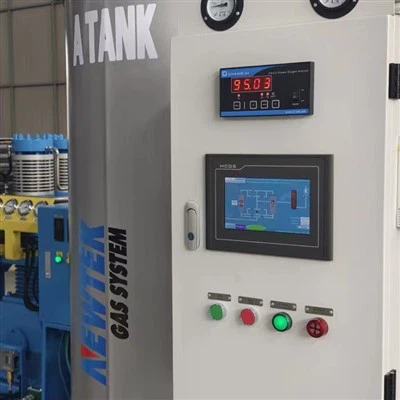
Gas Separation Process
The separation process is based on cyclic pressure variation inside two adsorption beds:
Cycle switching is controlled by PLC logic using pressure sensors (0–1.0 MPa range) and solenoid valves with response time ≤0.2 s.
Oxygen Injection Mechanism in Mineral Processing
Generated oxygen is delivered into mineral slurry systems through pipeline injection points:
Leaching tank bottom sparging ring: stainless steel 304 perforated pipe, 2–5 mm orifice size
Reactor side inlet diffuser: gas-liquid contact structure for bubble dispersion
When oxygen enters slurry (solid-liquid mixture containing ore particles and chemical reagents):
• Gas bubbles are dispersed into liquid phase under agitation (mechanical impeller 50–200 rpm depending on tank size)
• Oxygen dissolves into solution and increases dissolved oxygen concentration (DO control typically in mg/L range depending on process design)
• Oxidation reactions occur at mineral particle surfaces, especially sulfide minerals such as pyrite and chalcopyrite
This process directly affects oxidation rate and metal ion release kinetics in hydrometallurgical circuits.
System Components
Air Pretreatment Section
Coalescing filter element (borosilicate fiber media) removes oil aerosol ≤0.01 mg/m³ | Activated carbon adsorption layer captures hydrocarbon vapor residues | Refrigerated or adsorption dryer maintains compressed air dew point below -40°C to prevent zeolite pore blockage by water molecules
Adsorption Tower Assembly
Pressure vessel material: Q235B or SS304 (depending on corrosion environment) | Internal zeolite filling layer: 13X or lithium-based molecular sieve (0.4–0.8 mm granule size) | Gas distribution plate ensures uniform airflow velocity across bed cross-section to prevent channeling effect
Oxygen Storage and Stabilization Unit
Buffer tank absorbs flow fluctuation during valve switching phase | Equipped with pressure transmitter (accuracy ±1% FS) | Safety relief valve opens at design pressure threshold (typically 0.8 MPa)
Control System
PLC logic controls adsorption, equalization, and purge phases | Solenoid valve manifold distributes compressed air to each adsorption column | Feedback loop adjusts cycle time based on outlet oxygen purity signal
Working Environment Conditions
Designed for installation in mineral processing plants under the following conditions:
Ambient temperature range: 5°C–40°C
Dust-containing environment alignment
Continuous 24-hour operation mode
Containerized skid frame or concrete foundation with vibration isolation pads (10–20 mm)
Remote mining sites are fully supported where liquid oxygen logistics are not available.
Failure Modes & Process Stability
Measurable Degradation Links:
Moisture breakthrough → nitrogen leakage increase | Oil contamination → purity fluctuation | Valve timing drift (>0.5 s) → unstable outlet flow
Monitoring Instruments Used:
Oxygen analyzer (0–100% O₂, electrochemical)
Differential pressure sensors across beds
Flow meters at oxygen outlet pipeline (Nm³/h)
Installation and System Integration
System connection into mineral processing plant requires three interface points:
Compressed Air Interface
Connected to screw compressor discharge line (0.6–1.0 MPa). Requires upstream air receiver tank for pressure stabilization.
Oxygen Distribution Interface
Stainless steel pipeline (SS304 or HDPE). Connected to leaching tank manifold or sparging ring. Flow valve regulates injection rate.
Electrical Control Interface
380V / 50Hz standard industrial power supply (custom available). PLC communication via dry contact or Modbus protocol.
NEWTEK Engineering Configuration Capability
NEWTEK designs PSA oxygen systems based on process oxygen demand calculation rather than fixed equipment sizing. The workflow includes:

Validation Scope: Pressure retention test at 1.1× rated working pressure | Continuous cycling test of adsorption valves for ≥48 hours | Oxygen purity stabilization test under variable load conditions.
Application Scope
Technical Inquiry Data Required
System configuration is determined using the following process parameters: Ore processing capacity (tons per day) | Leaching tank volume and number of tanks (m³) | Target oxygen consumption rate or DO requirement | Plant altitude | Available electrical capacity (kW limit). Based on these inputs, PSA tower size, molecular sieve volume, and oxygen buffer tank capacity are calculated.
Engineering Inquiry Output
Provide your mineral processing flow sheet, leaching tank dimensions, or oxygen demand data. NEWTEK engineering team will calculate PSA adsorption tower sizing, compressor load configuration, and oxygen pipeline distribution layout based on your actual process conditions and operating cycle.
Hot Tags: oxygen generator for mineral processing, China oxygen generator for mineral processing manufacturers, suppliers, generator oxygene, industrial gas generator, industrial oxygen, industrial oxygen plant, PSA medical oxygen plant, psa oxigen generator